Introduction Unpacking the MIDI Drawbar Control Layout Diagram Rear Panel Front Panel What Are Drawbars? Historical Organ Information Using the MIDI Drawbar with the V3 Using the MIDI Drawbar With A Sequencer Using the MIDI Drawbar as a Continuous Controller Setting the MIDI Channel Specifications Warranty
The MIDI Drawbar provides a convenient method of accessing MIDI parameters and controls in real-time. It can be velcroed onto a keyboard controller allowing for an ergonomic placement of controls. MIDI audio mixing, MIDI lighting, and synthesizer control are some of the possible uses for the MIDI Drawbar.
The MIDI Drawbar makes an excellent companion to the V3 Tone Wheel Organ Synthesizer. Instant access to the most important V3 controls can easily be achieved by pushing labeled buttons, turning knobs, or moving drawbars.
Inside the MIDI Drawbar carton you will find:
Please return the warranty card soon after your purchase. This card will allow Voce to keep you informed of updates and new products.
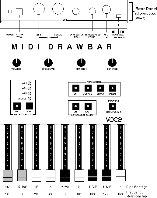
You'll find the following on the rear-panel:
There are three types of controls provided for the user on the MIDI Drawbar. Refer to the diagram on page 2. Section 1 contains nine push-button type controls with associated indicators, section 2 contains four rotary controls (knobs), and section 3 contains nine drawbars.
When used with the V3, these three types of controls provide the user with instant access to many of the V3's controls and parameters. The MIDI Drawbar can send fourteen different continuous-controller messages as well as nine different switch type MIDI control messages. The MERGE input provides a useful way of combining information from a keyboard or MIDI sequencer with MIDI data created by the front-panel controls.
This section will describe the use of drawbars in an organ context, for example, using the MIDI Drawbar with the V3 Tone Wheel Organ Synthesizer. The MIDI Drawbar need not be used for organ applications; its drawbars can be used for many application such as the volume faders of a MIDI mixer, or reverb time of an effects processor.
Tone-wheel organs use drawbars in a way which is analogous to the faders of a graphic equalizer. While a graphic equalizer modifies the timbre of a sound, drawbar synthesis creates timbres. This is actually a form of additive synthesis. Harmonic levels are increased by pulling drawbars out and decreased by pushing them in. As with a graphic equalizer, drawbars are also arranged with ascending frequencies from left to right. The 2nd drawbar from the left is an exception to this arrangement rule (see the Historical Organ Information section).
For example, if the leftmost drawbar is the only drawbar pulled out, the sound produced will be a low-frequency sine wave. A sine wave has no harmonic overtones. This makes sense; there is no other drawbar pulled out.
Organ registration conventions have developed over many centuries. Referring to the drawbar diagram on page 2, you will notice pipe footages associated with the drawbars. This notation is a throw-back to the days of pipe organs.
Pipe organs produce sound by introducing noise (turbulent air) into tuned resonators (pipes). An organ flute pipe sounds like a flute and is the most pure sounding (free of harmonics) type of organ pipe. This is the type of sound produced by playing a note on a tone-wheel organ with a single drawbar pulled out.
A flute pipe's frequency is roughly dependent on its length. The longer the pipe, the lower its frequency. Notice that the footages decrease for drawbars going from left to right. This agrees with the graphic equalizer analogy: The frequencies get higher going from left to right. If the pipe footages for the drawbars are divided into the first drawbar footage (16'), the relationship between the drawbar's harmonic frequencies can be seen. This relationship is shown in the diagram on page 2 below the footages.
Notice that the white drawbars have harmonic frequency relationships which are powers of two (2, 4, 8, and 16). This type of harmonic relationship is one in which the tones are related by octaves. The octave relationship is considered to be a "pure" relationship and that is why the white color is used to denote these drawbars. Drawbar harmonics which are not an octave apart from the white drawbars are indicated by their black-colored handles.
Many people wonder why the first drawbar (16') is not white and why the second drawbar appears to violate the low to high harmonic arrangement. Traditionally the 8' stop (drawbar) is thought of as the fundamental tone, therefore all harmonic frequencies below the fundamental tone or less than an octave above the fundamental are known as sub-harmonics. These subharmonic drawbars are designated by a brown-colored handle.
The MIDI Drawbar may be easily used with the VOCE® V3™ organ module. The factory default MIDI map called "Normal" is set to function with the MIDI Drawbar and requires almost no programming. The only exception is the BRAKE foot-switch which requires the V3's brake control number be set to 74.
The MIDI drawbar and the V3 are connected in the following manner:
The second step for configuring the MIDI Drawbars for use with the V3 is to set the MIDI channel selector switch. It should be set to the same channel as the keyboard or sequencer. See the MIDI drawbar manual if you are unsure about this operation.
The functions of the push-buttons when the MIDI Drawbar is used with the V3 are as follows:
The functions of the rotary controls when the MIDI Drawbar is used with the V3 are as follows:
The functions of the drawbars when the MIDI Drawbar is used with the V3 are as follows:
The best way to record drawbar changes and other MIDI control changes produce by the MIDI Drawbar is to record from the THRU output of the V3 (or the next module after the MIDI Drawbar). This will allow note on/off information as well as control changes to be saved in a MIDI sequence. Its best to press the RE-XMIT button at the beginning of a sequence in order to save the state of the MIDI Drawbars in the sequence.
To play back a MIDI sequence, connect the MIDI out of the sequencer directly to the V3 (or other sound module). It is also possible to view the push-button changes as they occur in the sequence by connecting the sequencer's MIDI output to the MIDI Drawbar input. The MIDI Drawbar is capable of displaying control changes it detects at its Merge Input which coincide with its push-buttons' control numbers. These changes will light the push-button indicators accordingly. For example: if control number 68 is detected at the Merge Input it will set the Rotating Speaker Slow/Fast indicator to reflect this change.
The MIDI Drawbar to be used as a general purpose MIDI control box and a merger. Fourteen continuous controllers and nine push-button / foot switch controllers can be merged with a keyboard or sequencer output. Many modern synthesizers and effect processors can use external continuous controllers to modify parameters in real time. Control of these parameters in real time has live performance applications, as well as reducing the time it takes to program sound modules and effect processors. The MIDI Drawbar also makes an excellent controller for MIDI lighting and mixing applications.
To use the MIDI Drawbar as a continuous controller: connect the device receiving MIDI data to MIDI OUT of the MIDI Drawbar. The MIDI Drawbar MERGE IN allows another MIDI controller's MIDI out to be connected and merged with the data generated by the MIDI Drawbar.
The functions of the push-button switches when used as a continuous controller are as follows:
| MIDI Data Value Sent | Function |
| 18 | Vibrato Mode, level 1 (C/V1 Lit, CHORUS Off) |
| 36 | Vibrato Mode, level 2 (C/V2 Lit, CHORUS Off) |
| 58 | Vibrato Mode, level 3 (C/V3 Lit, CHORUS Off) |
| 79 | Chorus Mode, level 1 (C/V1 and CHORUS Lit) |
| 100 | Chorus Mode, level 2 (C/V2 and CHORUS Lit) |
| 122 | Chorus Mode, level 3 (C/V3 and CHORUS Lit) |
The functions of the rotary controls when used as a continuous controller are as follows:
The function of the drawbars when used as a continuous controller are as follows:
| Control # | MMA use | MIDI DB |
| 7 | Volume | Volume |
| 8 | Balance | Expression Foot Pedal |
| 12 | - | Drawbar #1 (MAIN) |
| 13 | - | Drawbar #2 (MAIN) |
| 14 | - | Drawbar #3 (MAIN) |
| 15 | - | Drawbar #4 (MAIN) |
| 16 | GP cont #1 | Drawbar #5 (MAIN) |
| 17 | GP cont #2 | Drawbar #6 (MAIN) |
| 18 | GP cont #3 | Drawbar #7 (MAIN) |
| 19 | GP cont #4 | Drawbar #8 (MAIN) |
| 20 | - | Drawbar #9 (MAIN) |
| 21 | - | Drawbar #1 (AUX) |
| 22 | - | Drawbar #2 (AUX) |
| 23 | - | Drawbar #3 (AUX) |
| 24 | - | Drawbar #4 (AUX) |
| 25 | GP cont #1 | Drawbar #5 (AUX) |
| 26 | GP cont #2 | Drawbar #6 (AUX) |
| 27 | GP cont #3 | Drawbar #7 (AUX) |
| 28 | GP cont #4 | Drawbar #8 (AUX) |
| 29 | - | Drawbar #9 (AUX) |
| 68 | Legato | Fast/Slow |
| 70 | - | Percussion Decay |
| 71 | - | Percussion Volume |
| 72 | - | Percussion Harmonic |
| 73 | - | Percussion On/Off |
| 74 | - | Foot-Switch Brake |
| 89 | - | Key Click Volume |
| 90 | - | Hum |
| 91 | External Effects Depth | Distortion |
| 92 | Tremolo Depth | RS On/Off |
| 93 | Chorus Depth | Vibrato/Chorus Depth |
| 95 | Phaser Depth | Vibrato/Chorus On/Off |
| 102 | - | Save Function |
Set the MIDI Channel selector switch to the desired MIDI channel according to the following table:
| MIDI Channel | Switch Position |
| 1 | 1 |
| 2 | 2 |
| 3 | 3 |
| 4 | 4 |
| 5 | 5 |
| 6 | 6 |
| 7 | 7 |
| 8 | 8 |
| 9 | 9 |
| 10 | 10 |
| 11 | 11 |
| 12 | 12 |
| 13 | 13 |
| 14 | 14 |
| 15 | 15 |
| 16 | 0 |